
Single Contract · End-to-End Delivery
Same building.
187 days.
Concrete slab → live rack power
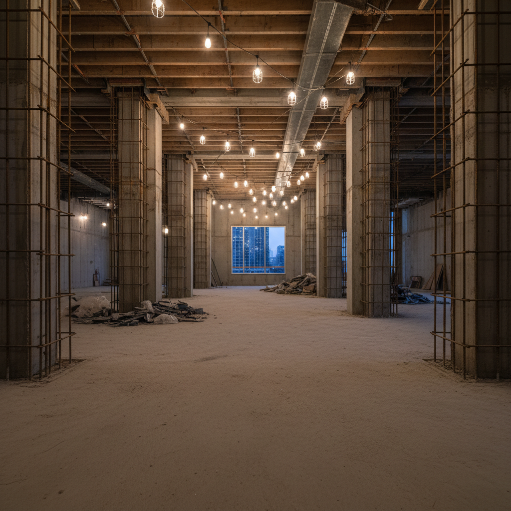
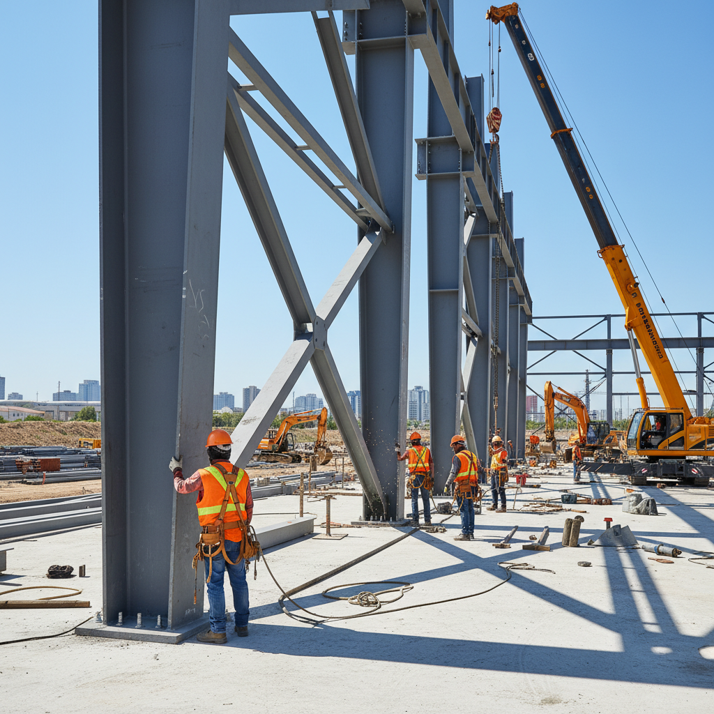
We start where most GCs won't — before the first shovel.
Site assessment, geotechnical investigation, utility coordination, grading, drainage, and pad preparation. Every civil decision downstream depends on getting this phase right. We self-perform or hold the single-point contract.
Scope of Work
- //Geotechnical report and bearing capacity confirmation
- //Utility service entrance coordination — power, fiber, water
- //Site grading to ±1/4" tolerance for raised floor prep
- //Storm drainage and retention per local AHJ
- //Temporary power and site facilities for construction
- //Environmental permits and AHJ pre-submittal meetings

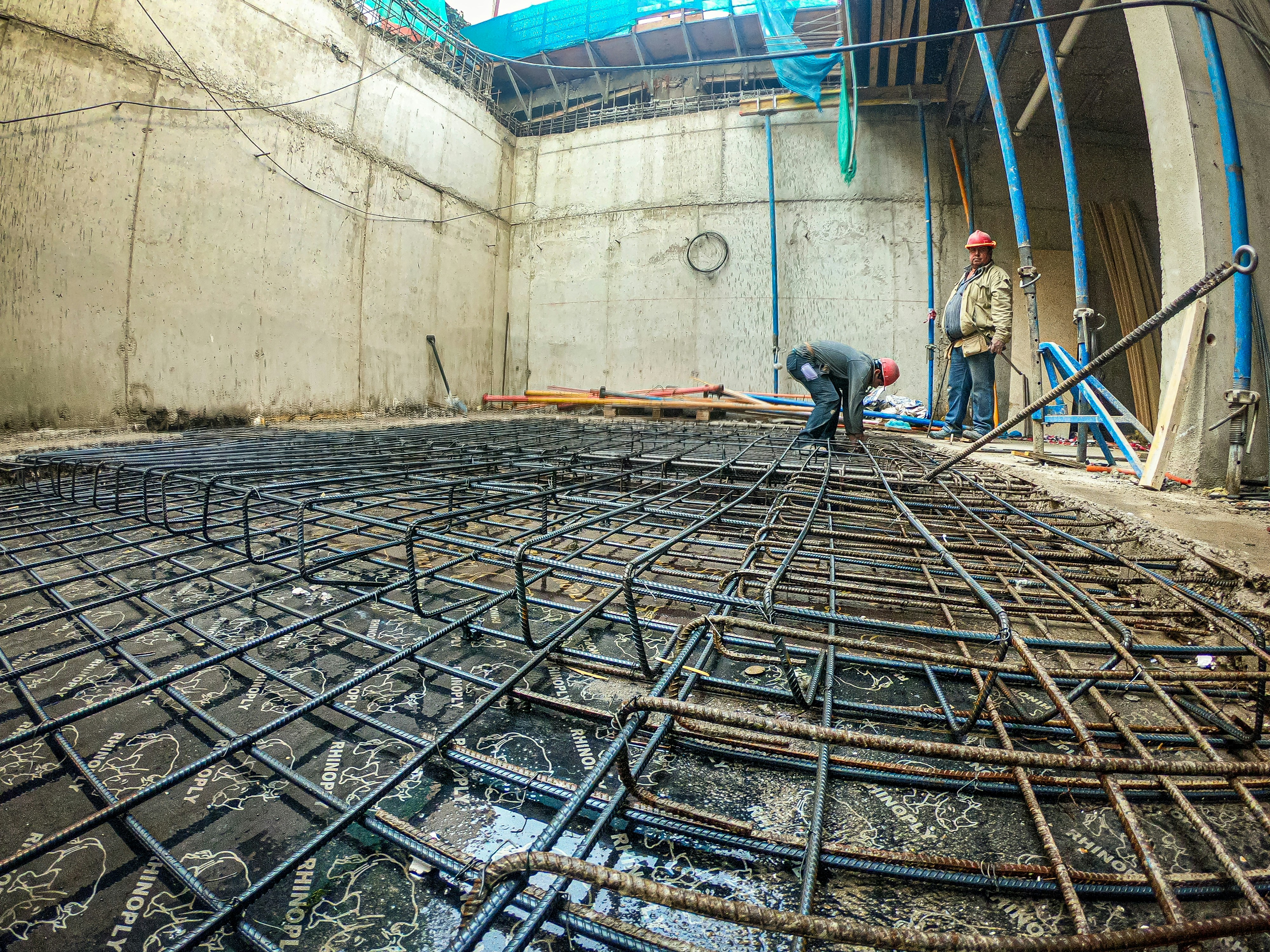
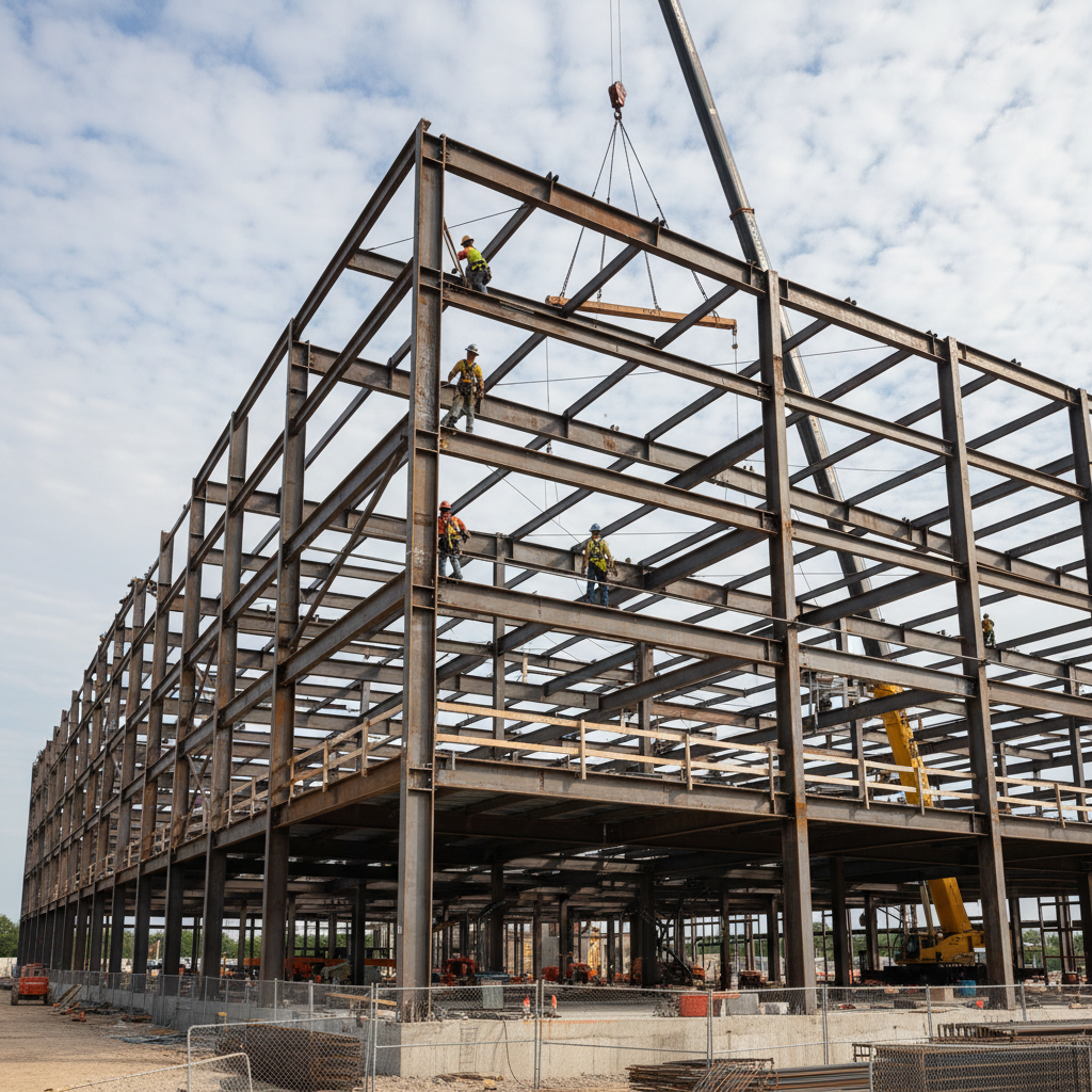
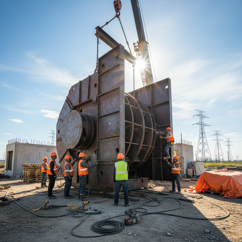
Steel up in days, not weeks. We track every weld.
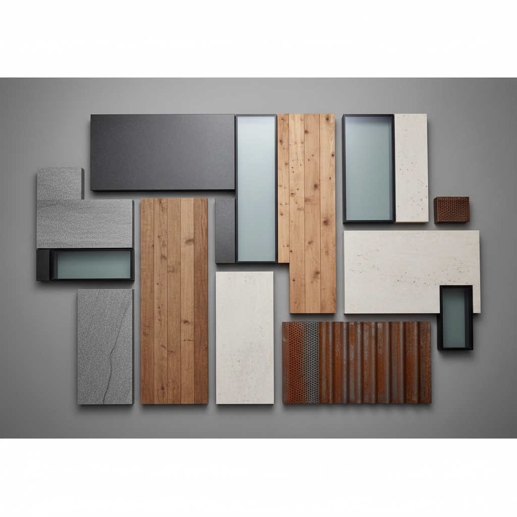
Structural steel erection, metal deck, concrete topping, building envelope (roof, walls, doors, loading docks), and all penetrations for future MEP rough-in. We coordinate structural and MEP in BIM before steel is ordered.
Scope of Work
- //Pre-engineered metal building or structural steel per structural EOR
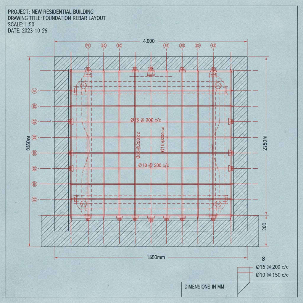
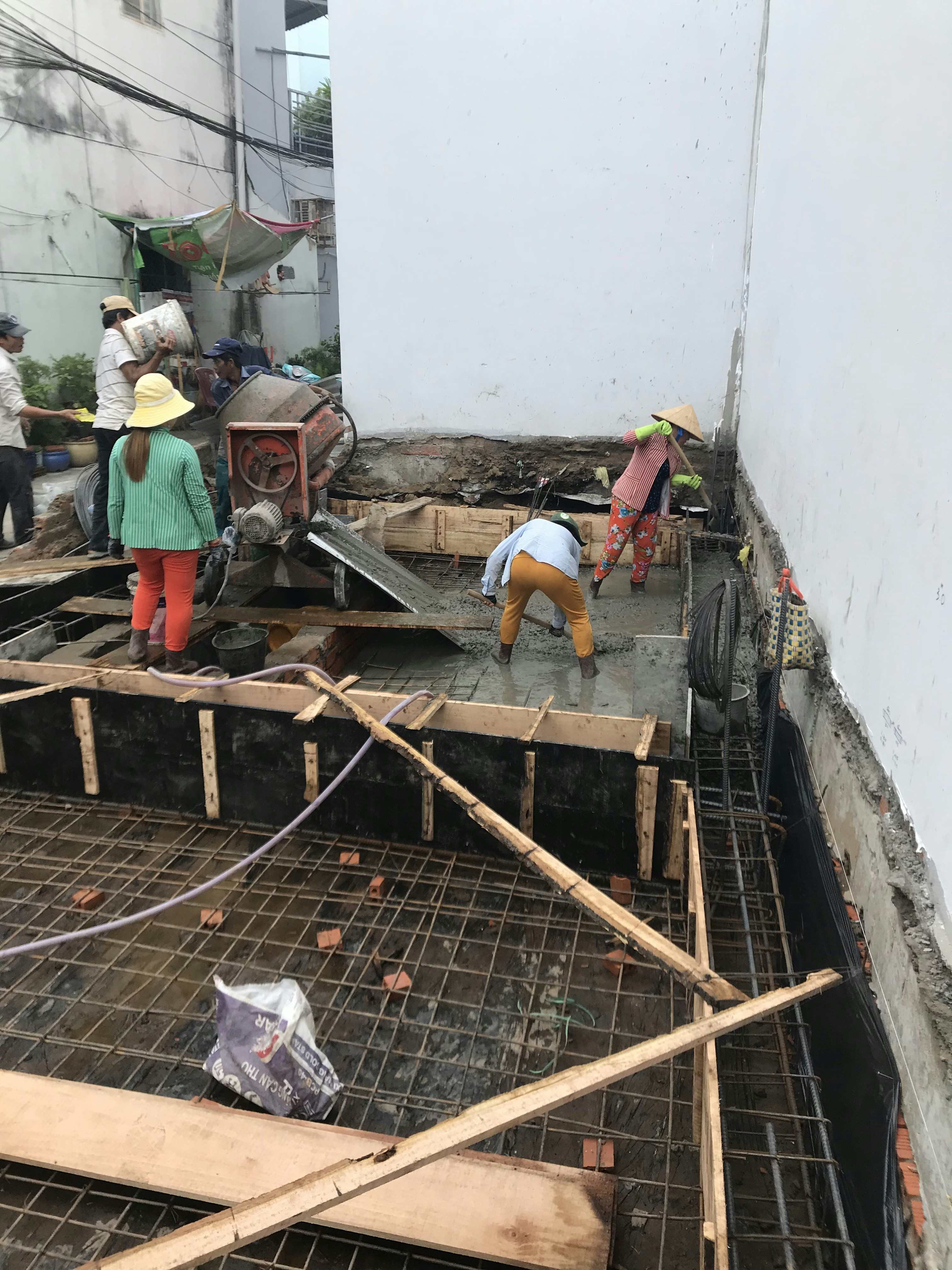
- //Metal deck and 4" concrete topping slab, wire-mesh reinforced
- //Standing-seam insulated roof system, R-30 minimum
- //Insulated metal panel wall system, 26-gauge min
- //Dock-height loading bays for generator and UPS delivery
- //All roof and wall penetrations core-drilled and sleeved pre-pour
- //BIM coordination model delivered at 75% CD

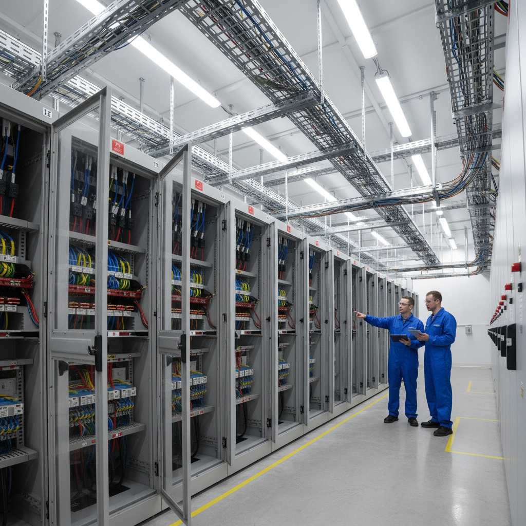
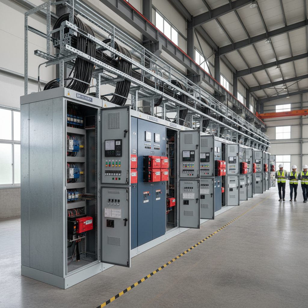
2N or N+1 — we size it, pull it, and test it.
Medium-voltage switchgear, transformers, UPS systems, PDUs, generator plant, and all associated cabling. We hold the electrical subcontract and manage it directly — no GC markup on a sub's sub.
Scope of Work
- //15kV–35kV medium-voltage service entrance, utility coordination
- //N+1 or 2N UPS topology per client spec, 500kW–4MW modules
- //Generator plant: 2MW per module, 72-hr fuel storage standard
- //Automatic transfer switching, static and rotary options
- //Overhead cable ladder and raised floor cable management
- //All conductors labeled per ANSI/TIA-606-C
- //Full load bank testing at 100% design capacity before handover

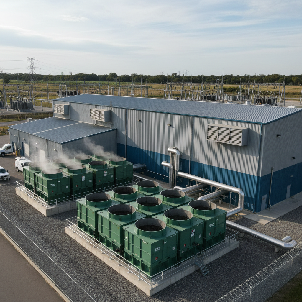
N+1 chiller plant. Every BTU accounted for.
Chilled water plant, CRAC/CRAH units, hot/cold aisle containment, humidification, and pre-action fire suppression. We design to PUE targets, not just cooling tons.
Scope of Work
- //N+1 chiller plant, 2MW cooling per module, variable speed drives
- //CRAH units, overhead or underfloor delivery per layout
- //Hot-aisle/cold-aisle containment curtains, floor-to-ceiling
- //Free-cooling economizer integration where climate allows
- //Building automation system (BAS) with DCIM integration points
- //Pre-action double-interlock suppression, clean agent optional
- //Full systems commissioning: TAB, BAS sequences, alarm verification

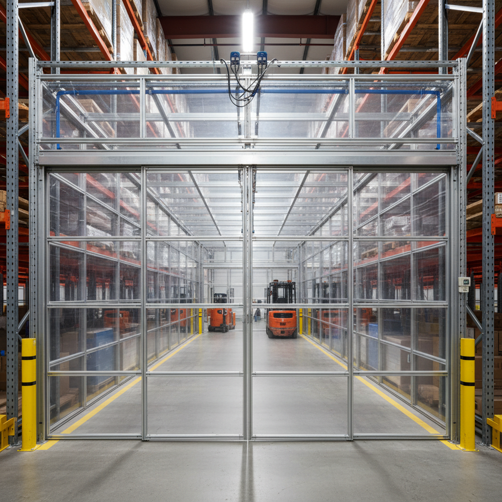


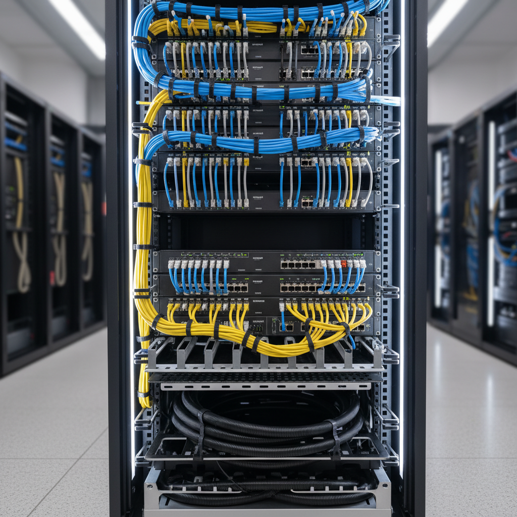
We hand you the keys when the last LED is green.
Raised floor installation, cabinet rows, structured cabling, patch panel labeling, DCIM sensor deployment, and full integrated systems testing. We don't leave until every circuit is verified under load.
Scope of Work
- //Raised access floor, 24" tile, 2,000 lb concentrated load rating
- //Cabinet rows per approved floor plan, grounded and bonded
- //Structured cabling: Cat6A copper and OS2 single-mode fiber
- //All patch panels labeled per ANSI/TIA-606-C, as-built delivered
- //DCIM sensor deployment: temperature, humidity, power at PDU level
- //Integrated systems test (IST) at 100% design load
- //Owner training, O&M manuals, and 1-year warranty on all systems

Ready to Move?
Your timeline starts with
one conversation.
Tell us your MW target, shell status, and energization deadline. We'll return a preliminary schedule and budget range within 48 hours.
Track Record
Numbers from the field,
not the pitch deck.
Every figure is drawn from completed project closeout reports. No estimates, no projections.
Projects Delivered
Since 2009
Total Capacity Built
Across all sites
Fastest Completion
4MW greenfield
On-Time Delivery
Last 5 years
States Active
Current pipeline
Still Evaluating?
Download our
completed project portfolio.
43 pages of completed build documentation — floor plans, commissioning reports, timeline actuals vs. estimates, and full-system single-line diagrams from six hyperscale and colocation projects across four states.
- //6 completed projects, 2MW–48MW range
- //Timeline actuals vs. original estimates
- //Full commissioning test reports
- //Reference contacts available on request